A következő címkéjű bejegyzések mutatása: RF - technika. Összes bejegyzés megjelenítése

2026. augusztus 9., vasárnap

XtremeDx H7113R Direct Conversion Transceiver

Key Architecture & Hardware Specs:

  • Receiver Architecture: Two coherent RF and DDC channels utilizing a hardware-level phasing-add matrix implemented directly inside the FPGA.

  • Processing: Dual-core ARM Cortex-A7 (1.2 GHz) dedicated to GUI handling and high-level DSP, paired with a custom FPGA fabric.

  • RF Conversion: 2x 16-bit LTC2208 ADC (122.88 MSPS) and 14-bit TxDAC utilizing full LVDS interfaces.

  • FPGA-Based Phasing-ADD Mode: A fully hardware-implemented, real-time, running inside the FPGA fabric. It processes the two coherent RX channels, allowing completely independent phase rotation and magnitude scaling per channel.

  • Interference Mitigation: CNLMS-based I/Q adaptive noise canceling (tested and validated using the same signal on RF inputs).

  • RF Routing: Two completely independent RX RF routing blocks, each integrating a switchable 20 dB preamplifier, 0.5 dB step attenuator, HPF, and direct ADC access via rear SMA connectors for subsampling/custom front-ends.

  • Power Amplifier: Delivers 120–140W PEP with 36–38 dB PEP IMD3 linearity across HF + 50 MHz bands.

  • Audio DSP: Separate 8-band EQ for both Rx and Tx AF signals.

  • Connectivity: High-bandwidth USB 3.0 (FT601) interface for direct FPGA-to-PC streaming (32-bit Sync FIFO implemented in VHDL) + USB 2.0 for ARM-to-PC communication. AF LINE output, CW-Key input.

  • Display: 7" TFT panel running a custom UI with a 70 fps refresh rate. It features 2D/3D spectrum views and a dedicated Polar Plot for the Phasing-ADD and ANC modes, visualizing the real-time magnitude and phase rotation per channel.

  • RF Routing and Linearity Performance: By routing the LTC2208 RF ADC without a preamplifier through the RF router, the system yields its maximum dynamic range and IIP3. Additionally, the 20 dB preamplifier maintains high IIP3 and OIP3 performance. With the internal PGA set to 0, the LTC2208 achieves a theoretical IIP3 of +48 dBm in this specific design.

Receiver Sensitivity (MDS Performance):

  • CW (100 Hz filter, NR ON): Highly discernible down to -136 dBm (Estimated nominal MDS: -133 to -136 dBm)

  • SSB (2.7 kHz filter, NR ON): Distinctly audible down to -126 dBm (Estimated nominal MDS: -123 to -125 dBm)


Hardware related details:

The RF/DSP board

Rx RF Router

140W PEP - RF power amplifier

Transceiver assembly


Red based Visual Theme - 3D spectrum plot


Blue based Visual Theme - 3D spectrum plot


\Red based Visual Theme - 2D spectrum plot - two Rx Channel View


Red based Visual Theme - 2D spectrum plot - one Rx Channel View


Red based Visual Theme - 3D spectrum plot - one Rx Channel View - Polar plot for Phasing ADD mode - magnitude scale and phase rotating per Rx Channel 


Green based Visual Theme - 3D spectrum plot - one Rx Channel View


Green based Visual Theme - 3D spectrum plot - one Rx Channel View - polar plot for ANC (automatic noise cancelling) mode with CNLMS - magnitude scaling and phase rotating possibilities per Rx Channel 


Green based Visual Theme - 3D spectrum plot - two Rx Channel View - Main Menu View


Green based Visual Theme - 3D spectrum plot - two Rx Channel View


Tx 8 band EQ


Videos


ANC test using the same signal on RF inputs


2025. szeptember 19., péntek

XtremeDx K160-1 RF Sampler Board

XtremeDx K160-1 RF Sampler Board - Dedicated for HF beamforming

- PCB - 16L, controlled impedance

- FPGA - Kintex 7 - K160 / K325 / K410 

- A/D - 4x 130 / 160 MSPS, 16b  - LTC2208 /  LTC2209 - LVDS connection

- D/A 1x 2 channel 500 MSPS, 14b - LVDS connection

- High speed connections - PCIe 3 x4, SFP, 2x USB3 (connected to MGT, and via FTDI FT601), 2x SATA, MIPI DPHY (output),

 - I/O CON { I2S, SPI (LVDS connections), GPIOs }, 2x PLL - LVDS out for processor board sync 

- System Clock - used for A/D and D/A and can be used for onboard synthesizer reference clock 

- Clock Synthesizer - used for D/A and for PCIe/SFP/(MGT) reference clock

- External System Clock input - U.FL connector - connected to Clock Distributor - for multiple board synchronization

- Sync'd PWR supply on separate board (not showed)

PCB Bottom side

PCB TOP side

PCB TOP side

    One HS signal layer 

                                                             A/D / D/A clocks and MIPI OUT 

2024. december 9., hétfő

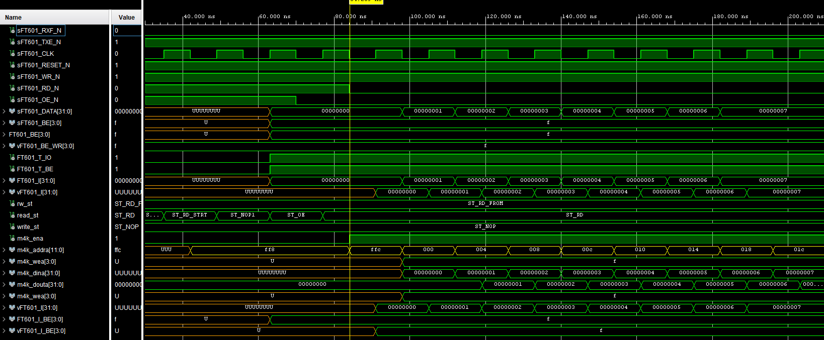
XtremeDx SDR - USB3/FT601 interface implementation

Implementation of USB3.0 Super-Speed 32 bits Sync FIFO interface 


- device connected

- 1V8 I/O voltage, 67 MHz bus CLK 

- written interface code in VHDL

- interface simulation using a few data bytes

- the loopback test is working with 1kB data

- PC app - FT601 loopback demo app


Zoomed


FT601 interface VHDL code - part 1 - the concept


2024. szeptember 6., péntek

HF Tx router

I2C controlled HF Tx router 

- 50 MHz Nyq filter

- Tx preamplifier

- preamplifier BIAS on/off by i2c

- direct signal routing on/off by i2c

- fixed value ATT on preamplifier in/out

- DC blocking and ESD protection at input


2024. szeptember 3., kedd

RF HF router

I2C controlled HF RF router for HF+50 MHz

4L controlled impedance PCB

Contains :

  • DC blocking, ESD protection, overvoltage protection,
  • NYQ filter, 
  • low noise linear voltage regulator for step-ATT
  • switchable 0.5dB-step-ATT, 
  • switchable HPF, 
  • switchable 20 dB preamplifier 
  • switchable RF-ports for external BPF module and for direct RF signal routing to ADC.


2024. június 22., szombat

XtremeDx H7113R Transceiver assembly

 The front panel and PCB for XtremeDx H7113R SDR

(not real scale)

    
4L PCB, The bottom layer

Top view, all layers


STM32 controller. Diff RF decoupled from 12VDC power supply. 7 ADC multiplexed inputs for DC U/I measurements as RFDSP voltage and current, PA voltage and current, VSWR voltages on VSWR bridge). Hole for one optical encoder. Holes for two mechanical rotary encoders - MULTI and ATT, one analog potentiometer for volume control on ADC. All inputs are RF and ESD protected. USART for communication with baseboard. (this architecture was tested in my H7R SDR) 


Front panel and PCB assembly


The front panel + the display


2024.09.dd


   2026.02 


202607


HF PA100 F101 2V0

 HF PA100 F101 2V0

HF power amplifier 3.5...50 MHz

- output power: 120W..150W PEP from 50 MHz down to 3.5 MHz (150W PEP on 14.2 MHz) 

- with driver section

- input power: 0..3 dBm

- min 30 dB PEP IMD3, max 36...38 dB PEP IMD3 


2026.07 - 2V0


2024. január 10., szerda

Two element delta-loop antenna for 20m band

Two element critical coupled delta-loop antenna for 20m band. 

The distance between elements is 3m. One element is radiator the another is the reflector. The radiation direction can be changed using relay.

The F/B ratio is 26..30 dB. The SWR is 1.2- 1.4.


2023. augusztus 23., szerda